
Page 254 - Rock Mechanics For Underground Mining
P. 254
EXCAVATION DESIGN IN STRATIFIED ROCK
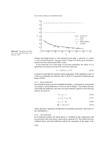
Figure 8.10 Normalised arch thick-
ness versus normalised span (after
Sofianos, 1996).
between load depth fraction, n, and normalised room span, s n (given by s/t, where
t is the roof bed thickness). The plot shown in Figure 8.8 shows good consistency
between the finite element and UDEC results.
It was found that, for a wide range of roof beam geometries, the values of n at
equilibrium lie between 0.12 and 0.30, and fit the expression
n = 1/(0.22 s n + 2.7) (8.15)
It should be noted that this equation returns magnitudes of the equilibrium value of
n that are considerably less than the value of about 0.75 reported by Diederichs and
Kaiser (1999a).
8.5.1 Beam deflection
In roof beam formation, an arch of undeflected height z o is shortened by an increment
L during a vertical deflection to form an arch of height z. The relation between
arch height and deflection, and some associated relations required in the following
analysis, are given by
= z 0 − z (8.16)
z
z n = = z on − n (8.17)
t
2
z on = 1 − n (8.18)
3
1 2
M R = xx nt z n (8.19)
2
where subscript n represents normalisation of geometric parameters with respect to
the roof thickness t.
8.5.2 Arch geometry
In its deflected position, the lateral thrusts T mobilised in the compression arch
are associated with axial stresses which satisfy equation 8.13. The relation between
mobilised thrust and beam deflection exploits the assumption of the shape of the
236