Page 250 - Rock Mechanics For Underground Mining
P. 250

EXCAVATION DESIGN IN STRATIFIED ROCK

                                        force, V , be balanced by the resisting moment M R of the distributed end loads,
                                        i.e.
                                                                  1    2        1
                                                             M A =   ts = M R =   f c ntz              (8.5)
                                                                  8             2
                                        or

                                                                         1  s 2
                                                                     f c =                             (8.6)
                                                                         4 nz
                                        where f c is the maximum compressive stress acting in the beam, operating at the
                                        bottom edge at the abutment and at the top edge at the centre of the span.
                                          Analysis of the three modes of roof instability involves determination of f c , n and z.
                                        Following Sofianos (1996), Diederichs and Kaiser (1999) showed that the assumption
                                        of Evans of n = 0.5 was inadequate, that the iterative method proposed by Brady and
                                        Brown (1985) was appropriate for small deflections, but that convergence and stability
                                        in the solution procedure could be improved.
                                          The solution procedure begins with an assumption of the initial moment arm prior
                                        to deflection, z o , which is given by

                                                                             2
                                                                   z o = t 1 − n                       (8.6)
                                                                             3
                                        The length L of the parabolic reaction arch is given by
                                                                            8 z 2 o
                                                                    L = s +                            (8.7)
                                                                            3 s
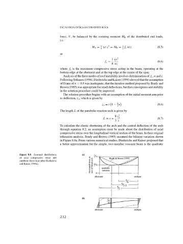
                                        To calculate the elastic shortening of the arch and the central deflection of the arch
                                        through equation 8.2, an assumption must be made about the distribution of axial
                                        compressive stress over the longitudinal vertical section of the beam. In their original
                                        relaxation analysis, Brady and Brown (1985) assumed the bilinear variation shown
                                        in Figure 8.8a. From various numerical studies, Diederichs and Kaiser proposed that
                                        a better approximation for the simple, two-member voussoir beam is the quadratic


              Figure 8.8  Assumed distributions
              of axial compressive stress and
              parabolic thrust line (after Diederichs
              and Kaiser, 1999a).


                                        232
   245   246   247   248   249   250   251   252   253   254   255