
Page 247 - Rock Mechanics For Underground Mining
P. 247
ROOF BED DEFORMATION MECHANICS
lateral thrust, reflects the significance of induced thrust in determining the subsequent
performance of the voussoir beam. The linear range of response (2–7) was reversible,
and extrapolates downwards to the original loading conditions. Past the peak load
capacity of the beam (10), the reducing lateral thrust caused by local spalling results
in reduced vertical load capacity for the beam.
This and other tests conducted by Sterling allow formulation of the following
principles concerning roof rock behaviour over mined spans:
(a) roof beds cannot be simulated by continuous, elastic beams or plates, since their
behaviour is dominated by the blocks (voussoirs) generated by natural cross
joints or induced transverse fractures;
(b) roof bed behaviour is determined by the lateral thrusts generated by deflection,
under gravity loading, of the voussoir beam against the confinement of the abut-
ting rock;
(c) a voussoir beam behaves elastically (i.e. the lateral thrust – vertical deflection
plot is linear and reversible) over the range of its satisfactory performance, the
upper limit of which approaches the peak transverse load capacity;
(d) for a voussoir beam with low span/thickness ratio, the most likely failure mode
is shear failure at the abutments;
(e) for a roof with high span/thickness ratio, roof span stability is limited by the
possibility of buckling of the beam, with no significant spalling of central or
abutment voussoirs;
(f) a roof with low rock material strength or moderate span/thickness ratio may fail
by crushing or spalling of central or abutment voussoirs.
An alternative study of the performance of excavations in bedded and jointed rock
led to conclusions consistent with the model developed from experimental observa-
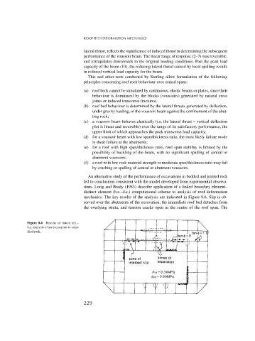
tions. Lorig and Brady (1983) describe application of a linked boundary element–
distinct element (b.e.–d.e.) computational scheme to analysis of roof deformation
mechanics. The key results of the analysis are indicated in Figure 8.6. Slip is ob-
served over the abutments of the excavation, the immediate roof bed detaches from
the overlying strata, and tension cracks open in the centre of the roof span. The
Figure 8.6 Results of linked d.e.–
b.e. analysis of an excavation in strat-
ified rock.
229