
Page 246 - Rock Mechanics For Underground Mining
P. 246
EXCAVATION DESIGN IN STRATIFIED ROCK
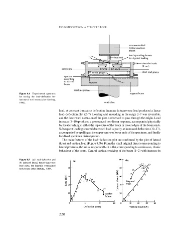
Figure 8.4 Experimental apparatus
for testing the load–deflection be-
haviour of roof beams (after Sterling,
1980).
load, at constant transverse deflection. Increase in transverse load produced a linear
load–deflection plot (2–7). Loading and unloading in the range 2–7 was reversible,
and the downward extension of the plot is observed to pass through the origin. Load
increase (7–10) produced a pronounced non-linear response, accompanied physically
by local crushing at either the top centre of the beam or lower edges of the beam ends.
Subsequent loading showed decreased load capacity at increased deflection (10–17),
accompanied by spalling at the upper centre or lower ends of the specimen, and finally
localised specimen disintegration.
The main features of the load–deflection plot are confirmed by the plot of lateral
thrust and vertical load (Figure 8.5b). From the small original thrust corresponding to
lateral prestress, the initial response (0–1) is flat, corresponding to continuous, elastic
behaviour of the beam. Central vertical cracking of the beam (1–2) with increase in
Figure 8.5 (a) Load–deflection and
(b) induced lateral thrust–transverse
load plots, for laterally constrained
rock beams (after Sterling, 1980).
228