
Page 248 - Rock Mechanics For Underground Mining
P. 248
EXCAVATION DESIGN IN STRATIFIED ROCK
distributions of normal stress and shear stress in the roof bed were generally consis-
tent with the voussoir beam model proposed by Evans (1941), and considered below.
One notable difference was observed between the Evans model and the results of
the numerical study. This was that bed separation, proposed by Evans to include
the complete excavation span, was indicated over only the centre of the span in the
computational analysis.
8.4 Roof design procedure for plane strain
A design procedure for roof beams was developed by Evans (1941) and modified
by Beer and Meek (1982). Subsequently Sofianos (1996) and Diederichs and Kaiser
(1999a) noted some limitations in a simplified version of Beer and Meek’s method pre-
sented by Brady and Brown (1985) and proposed alternative ways of tackling the static
indeterminacy of roof bed analysis. The design procedures proposed here draw on the
approaches of Evans, Brady and Brown, Diederichs and Kaiser, and Sofianos. More
comprehensive analyses are reported by Sofianos (1996) and Diederichs and Kaiser
(1999a). It should be noted that the solution procedures of Sofianos and Diederichs
and Kaiser assume different conceptual models for a roof beam, and consequently
the results of analyses of static stability and beam deflection differ considerably. A
valuable discussion of the differences between the two models is provided by Sofianos
(1999) and Diederichs and Kaiser (1999b). The analysis which follows immediately is
based on the formulation of Diederichs and Kaiser, which is a revision and extension
of that proposed by Brady and Brown (1985).
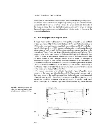
The voussoir beam model for a roof bed is illustrated in Figure 8.7a, and the forces
operating in the system are defined in Figure 8.7b. The essential idea conveyed in
the figures is that, in the equilibrium condition, the lateral thrust is not transmitted
either uniformly or axially through the beam cross section. The section of the beam
transmitting lateral load is assumed to be approximated by the parabolic arch traced
on the beam span. Since various experimental investigations support the intuitive
Figure 8.7 Free body diagrams and
notation for analysis of voussoir beam
(after Diederichs and Kaiser, 1999a).
230