
Page 59 - Rock Mechanics For Underground Mining
P. 59
GRAPHICAL REPRESENTATION OF BIAXIAL STRESS
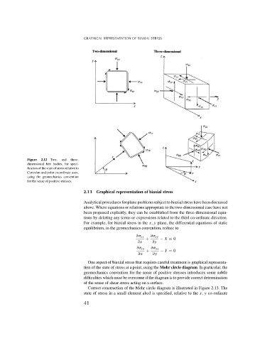
Figure 2.12 Two- and three-
dimensional free bodies, for speci-
fication of the state of stress relative to
Cartesian and polar co-ordinate axes,
using the geomechanics convention
for the sense of positive stresses.
2.13 Graphical representation of biaxial stress
Analytical procedures for plane problems subject to biaxial stress have been discussed
above. Where equations or relations appropriate to the two-dimensional case have not
been proposed explicitly, they can be established from the three-dimensional equa-
tions by deleting any terms or expressions related to the third co-ordinate direction.
For example, for biaxial stress in the x, y plane, the differential equations of static
equilibrium, in the geomechanics convention, reduce to
∂ xx ∂ xy
+ − X = 0
∂x ∂y
∂ xy ∂ yy
+ − Y = 0
∂x ∂y
One aspect of biaxial stress that requires careful treatment is graphical representa-
tion of the state of stress at a point, using the Mohr circle diagram. In particular, the
geomechanics convention for the sense of positive stresses introduces some subtle
difficulties which must be overcome if the diagram is to provide correct determination
of the sense of shear stress acting on a surface.
Correct construction of the Mohr circle diagram is illustrated in Figure 2.13. The
state of stress in a small element abcd is specified, relative to the x, y co-ordinate
41