Page 60 - Rock Mechanics For Underground Mining
P. 60

STRESS AND INFINITESIMAL STRAIN


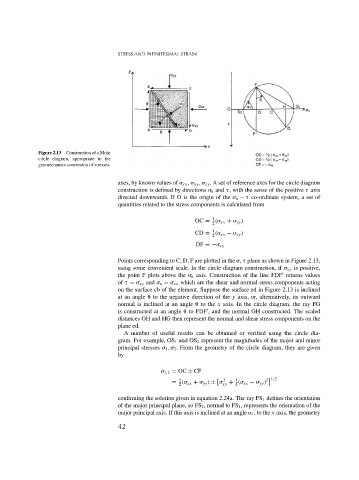
              Figure 2.13  Construction of a Mohr
              circle diagram, appropriate to the
              geomechanics convention of stresses.

                                        axes, by known values of   xx ,   yy ,   xy . A set of reference axes for the circle diagram
                                        construction is defined by directions   n and  , with the sense of the positive   axis
                                        directed downwards. If O is the origin of the   n −   co-ordinate system, a set of
                                        quantities related to the stress components is calculated from

                                                                       1
                                                                  OC = (  xx +   yy )
                                                                       2
                                                                       1
                                                                  CD = (  xx −   yy )
                                                                       2
                                                                  DF =−  xy
                                        Points corresponding to C, D, F are plotted in the  ,   plane as shown in Figure 2.13,
                                        using some convenient scale. In the circle diagram construction, if   xy is positive,

                                        the point F plots above the   n axis. Construction of the line FDF returns values
                                        of   =   xy and   n =   xx which are the shear and normal stress components acting
                                        on the surface cb of the element. Suppose the surface ed in Figure 2.13 is inclined
                                        at an angle 
 to the negative direction of the y axis, or, alternatively, its outward
                                        normal is inclined at an angle 
 to the x axis. In the circle diagram, the ray FG
                                        is constructed at an angle 
 to FDF , and the normal GH constructed. The scaled

                                        distances OH and HG then represent the normal and shear stress components on the
                                        plane ed.
                                          A number of useful results can be obtained or verified using the circle dia-
                                        gram. For example, OS 1 and OS 2 represent the magnitudes of the major and minor
                                        principal stresses   1 ,   2 . From the geometry of the circle diagram, they are given
                                        by

                                                        1,2 = OC ± CF
                                                                               1
                                                                           2
                                                            1


                                                          = (  xx +   yy ) ±   + (  xx −   yy ) 2 1/2
                                                            2              xy  4
                                        confirming the solution given in equation 2.24a. The ray FS 1 defines the orientation
                                        of the major principal plane, so FS 2 , normal to FS 1 , represents the orientation of the
                                        major principal axis. If this axis is inclined at an angle   1 , to the x axis, the geometry
                                        42
   55   56   57   58   59   60   61   62   63   64   65