
Page 69 - Rock Mechanics For Underground Mining
P. 69
IMPORTANT GEOMECHANICAL PROPERTIES OF DISCONTINUITIES
the wall rock and should be taken into account in rock mass classification schemes
(see section 3.7).
It is common in rock mechanics to use the term discontinuity as a collective term
for all fractures or features in a rock mass such as joints, faults, shears, weak bedding
planes and contacts that have zero or relatively low tensile strengths. This terminology
will be used here and will be departed from only when it is necessary to identify the
geological origin of the structural feature being discussed.
3.3 Important geomechanical properties of discontinuities
This section lists and discusses briefly the most important of those properties of dis-
continuities that influence the engineering behaviour of rock masses. For a fuller
discussion of these properties, the reader should consult the document ‘Suggested
methods for the quantitative description of discontinuities in rock masses’ prepared
by the Commission on Standardization of Laboratory and Field Tests, International
Society for Rock Mechanics (1978a), subsequently referred to as the ISRM Commis-
sion (1978a).
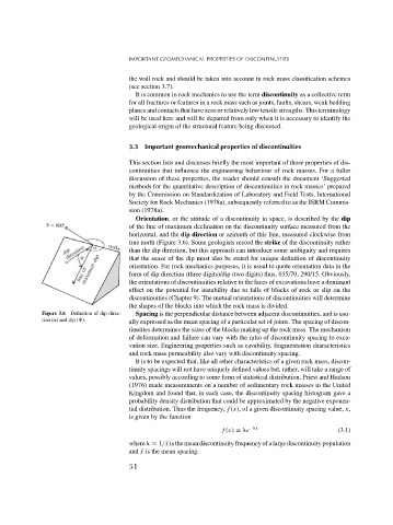
Orientation, or the attitude of a discontinuity in space, is described by the dip
of the line of maximum declination on the discontinuity surface measured from the
horizontal, and the dip direction or azimuth of this line, measured clockwise from
true north (Figure 3.6). Some geologists record the strike of the discontinuity rather
than the dip direction, but this approach can introduce some ambiguity and requires
that the sense of the dip must also be stated for unique definition of discontinuity
orientation. For rock mechanics purposes, it is usual to quote orientation data in the
form of dip direction (three digits)/dip (two digits) thus, 035/70, 290/15. Obviously,
the orientations of discontinuities relative to the faces of excavations have a dominant
effect on the potential for instability due to falls of blocks of rock or slip on the
discontinuities (Chapter 9). The mutual orientations of discontinuities will determine
the shapes of the blocks into which the rock mass is divided.
Figure 3.6 Definition of dip direc- Spacing is the perpendicular distance between adjacent discontinuities, and is usu-
tion ( ) and dip ( ). ally expressed as the mean spacing of a particular set of joints. The spacing of discon-
tinuities determines the sizes of the blocks making up the rock mass. The mechanism
of deformation and failure can vary with the ratio of discontinuity spacing to exca-
vation size. Engineering properties such as cavability, fragmentation characteristics
and rock mass permeability also vary with discontinuity spacing.
It is to be expected that, like all other characteristics of a given rock mass, discon-
tinuity spacings will not have uniquely defined values but, rather, will take a range of
values, possibly according to some form of statistical distribution. Priest and Hudson
(1976) made measurements on a number of sedimentary rock masses in the United
Kingdom and found that, in each case, the discontinuity spacing histogram gave a
probability density distribution that could be approximated by the negative exponen-
tial distribution. Thus the frequency, f (x), of a given discontinuity spacing value, x,
is given by the function
f (x) = e − x (3.1)
where 1/¯ x is the mean discontinuity frequency of a large discontinuity population
and ¯ x is the mean spacing.
51