Page 72 - Rock Mechanics For Underground Mining
P. 72

ROCK MASS STRUCTURE AND CHARACTERISATION

                                                         Table 3.1  Classification of discontinuity spacing.

                                                         Description             Spacing (mm)
                                                         extremely close spacing     <20
                                                         very close spacing         20–60
                                                         close spacing              60–200
                                                         moderate spacing          200–600
                                                         wide spacing              600–2000
                                                         very wide spacing        2000–6000
                                                         extremely wide spacing      >6000


                                                        Table 3.2  Classification of discontinuity persistence.

                                                        Description         Modal trace length (m)
                                                        very low persistence            <1
                                                        low persistence                 1–3
                                                        medium persistence              3–10
                                                        high persistence               10–20
                                                        very high persistence            20


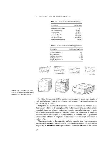
              Figure 3.9  Illustration of persis-
              tence of various sets of discontinuities
              (after ISRM Commission, 1978a).

                                          The ISRM Commission (1978a) uses the most common or modal trace lengths of
                                        each set of discontinuities measured on exposures (section 3.4.1) to classify persis-
                                        tence according to Table 3.2.
                                          Roughness is a measure of the inherent surface unevenness and waviness of the
                                        discontinuity relative to its mean plane. The wall roughness of a discontinuity has a
                                        potentially important influence on its shear strength, especially in the case of undis-
                                        placed and interlocked features (e.g. unfilled joints). The importance of roughness
                                        declines with increasing aperture, filling thickness or previous shear displacement.
                                        The important influence of roughness on discontinuity shear strength is discussed in
                                        section 4.7.2.
                                          When the properties of discontinuities are being recorded from observations made
                                        on either drill core or exposures, it is usual to distinguish between small-scale surface
                                        irregularity or unevenness and larger-scale undulations or waviness of the surface
                                        54
   67   68   69   70   71   72   73   74   75   76   77