
Page 77 - Rock Mechanics For Underground Mining
P. 77
COLLECTING STRUCTURAL DATA
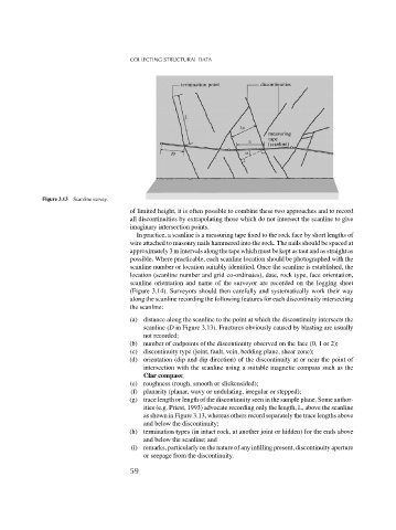
Figure 3.13 Scanline survey.
of limited height, it is often possible to combine these two approaches and to record
all discontinuities by extrapolating those which do not intersect the scanline to give
imaginary intersection points.
In practice, a scanline is a measuring tape fixed to the rock face by short lengths of
wire attached to masonry nails hammered into the rock. The nails should be spaced at
approximately 3 m intervals along the tape which must be kept as taut and as straight as
possible. Where practicable, each scanline location should be photographed with the
scanline number or location suitably identified. Once the scanline is established, the
location (scanline number and grid co-ordinates), date, rock type, face orientation,
scanline orientation and name of the surveyor are recorded on the logging sheet
(Figure 3.14). Surveyors should then carefully and systematically work their way
along the scanline recording the following features for each discontinuity intersecting
the scanline:
(a) distance along the scanline to the point at which the discontinuity intersects the
scanline (D in Figure 3.13). Fractures obviously caused by blasting are usually
not recorded;
(b) number of endpoints of the discontinuity observed on the face (0, 1 or 2);
(c) discontinuity type (joint, fault, vein, bedding plane, shear zone);
(d) orientation (dip and dip direction) of the discontinuity at or near the point of
intersection with the scanline using a suitable magnetic compass such as the
Clar compass;
(e) roughness (rough, smooth or slickensided);
(f) planarity (planar, wavy or undulating, irregular or stepped);
(g) trace length or length of the discontinuity seen in the sample plane. Some author-
ities (e.g. Priest, 1993) advocate recording only the length, L, above the scanline
as shown in Figure 3.13, whereas others record separately the trace lengths above
and below the discontinuity;
(h) termination types (in intact rock, at another joint or hidden) for the ends above
and below the scanline; and
(i) remarks, particularly on the nature of any infilling present, discontinuity aperture
or seepage from the discontinuity.
59