
Page 78 - Rock Mechanics For Underground Mining
P. 78
ROCK MASS STRUCTURE AND CHARACTERISATION
Line No.: _________ North: ___________ Bench face/wall dip: ____________ Page: _____ of ________
Bearing: __________ East: ____________ Bench face/wall dip dir: _________ By:__________________
Plunge:___________ Censoring levels (m): up ________ down_______ Date: ________________
Elev: ____________ Location: ___________________________ Start: ___________ Finish: __________
LOCATION STRUCTURE GEOMETRY REMARKS
Above Trace Length Below
Dist (m) Endpoints Type Dip Dir Dip Rock Rough Plan T1 T2 (m) T1 T2
NOTATION USED:
Endpoint Locations Structure Type Roughness Planarity T1 (Termination) T2
0 Transecting J Joint B Bedding R Rough P Planar AJ Another joint L Low angle (<20°)
1 Intersecting V Vein S Shear S Smooth W Wavy IR Intact rock H High angle (>20°)
2 Contained F Fault C Contact SL Slickensided I Irregular FC Floor censored UN Unknown
BX Blast induced RC Roof censored
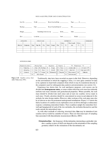
Figure 3.14 Scanline survey sheet Traditionally, data have been recorded on paper in the field. However, depending
(after Villaescusa, 1991).
on the environment in which the mapping is done, it is now quite common for data
to be captured on hand held computers from which it may be transferred directly to
the computers used for subsequent data analysis and presentation (see section 3.6).
Experience has shown that, for rock mechanics purposes, rock masses can be
divided into homogeneous zones, or zones within which the rock mass has relatively
uniform rock mass structure and geotechnical properties. Where possible, the rock
mass should be divided into such zones and at least one scanline survey made in
each zone. Clearly, attention should be concentrated on areas in and adjacent to the
orebody for mine design studies. However, other sections of the rock mass may also
be of interest as sites for permanent underground installations. Figure 3.15 shows the
likely locations of scanlines in an exploration cross cut driven through a sedimentary
sequence containing mineralised shales. These scanlines sample the immediate foot-
wall and hangingwall of each of the two orebodies, the orebodies themselves and the
rocks outside the mineralised zone.
As with other methods of collecting structural data, bias may be introduced into
scanline survey results by a number of causes. There are four main types of sampling
bias associated with discontinuity measurement (Brown, 2003):
Orientation bias – the frequency of discontinuities intersecting a particular win-
dow, scanline or piece of drill core depends on the orientation of the sampling
geometry relative to the orientation of the discontinuity set.
60