
Page 79 - Rock Mechanics For Underground Mining
P. 79
COLLECTING STRUCTURAL DATA
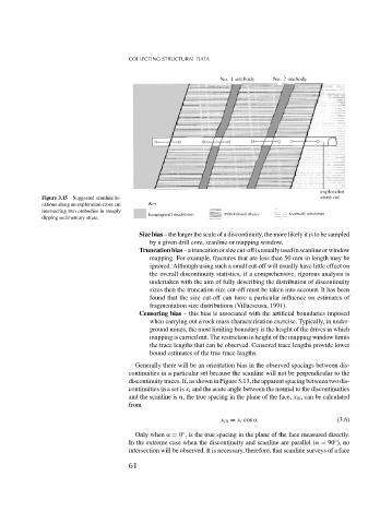
Figure 3.15 Suggested scanline lo-
cations along an exploration cross cut
intersecting two orebodies in steeply
dipping sedimentary strata.
Size bias – the larger the scale of a discontinuity, the more likely it is to be sampled
by a given drill core, scanline or mapping window.
Truncationbias–atruncationorsizecut-offisusuallyusedinscanlineorwindow
mapping. For example, fractures that are less than 50 mm in length may be
ignored. Although using such a small cut-off will usually have little effect on
the overall discontinuity statistics, if a comprehensive, rigorous analysis is
undertaken with the aim of fully describing the distribution of discontinuity
sizes then the truncation size cut-off must be taken into account. It has been
found that the size cut-off can have a particular influence on estimates of
fragmentation size distributions (Villaescusa, 1991).
Censoring bias – this bias is associated with the artificial boundaries imposed
when carrying out a rock mass characterisation exercise. Typically, in under-
ground mines, the most limiting boundary is the height of the drives in which
mapping is carried out. The restriction in height of the mapping window limits
the trace lengths that can be observed. Censored trace lengths provide lower
bound estimates of the true trace lengths.
Generally there will be an orientation bias in the observed spacings between dis-
continuities in a particular set because the scanline will not be perpendicular to the
discontinuity traces. If, as shown in Figure 3.13, the apparent spacing between two dis-
continuities in a set is x i and the acute angle between the normal to the discontinuities
and the scanline is , the true spacing in the plane of the face, x i0 , can be calculated
from
x i0 = x i cos (3.6)
◦
Only when = 0 , is the true spacing in the plane of the face measured directly.
◦
In the extreme case when the discontinuity and scanline are parallel ( = 90 ), no
intersection will be observed. It is necessary, therefore, that scanline surveys of a face
61