
Page 229 - Root Cause Failure Analysis
P. 229
Control Valves 217
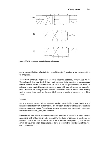
Figure 17-1 6 Actuator-controlled valve schematics.
return ensures that the valve is in its neutral (i.e., right) position when the solenoid is
de-energized.
The bottom schematic represents a double-solenoid, detented, two-position valve.
The solenoids are used to shift the valve between its two positions. A secondary
device, called a detent, is used to hold the valve in its last position until the alternate
solenoid is energized. Detent configuration varies with the valve type and manufac-
turer. However, all configurations prevent the valve’s control device from moving
until a strong force, such as that provided by the solenoid, overcomes its locking
force.
Actuators
As with process-control valves, actuators used to control fluid-power valves have a
fundamental influence on performance. The actuators must provide positive, real-time
response to control inputs. The primary types of actuators used to control fluid-power
valves are mechanical, pilot, and solenoid.
Mechanical The use of manually controlled mechanical valves is limited in both
pneumatic and hydraulic circuits. Generally, this type of actuator is used only on
isolation valves that are activated when the circuit or fluid-power system is shut
down for repair or when direct operator input is required to operate one of the sys-
tem components.