
Page 228 - Root Cause Failure Analysis
P. 228
216 Root Cause Failure Analysis
P T P T P T
U'JI El
P
T
T
P
P T
Type 3 Type 4 Type 6
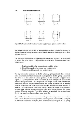
Figure 17-15 Schematic for center or neutral configurations of three-position valves.
mits the full pressure and volume on the upstream side of the valve to flow directly to
the return line and storage reservoir. This is the recommended center position for most
hydraulic circuits.
The schematic affixed to the valve includes the primary and secondary actuators used
to control the valve. Figure 17-16 provides the schematics for three actuator-con-
trolled valves:
1. Double-solenoid, spring-centered, three-position valve;
2. Solenoid-operated, spring-return, two-position valve;
3. Double-solenoid, detented, two-position valve.
The top schematic represents a double-solenoid, spring-centered, three-position
valve. When neither of the two solenoids is energized, the double springs ensure that
the valve is in its center or neutral position. In this example, a Type 0 (see
Figure 17-1 5) configuration is used. This neutral-position configuration equalizes the
pressure through the valve. Since the pressure port is open to both work ports and the
return line, pressure is equalized throughout the system. When the left or primary
solenoid is energized, the valve shifts to the left-hand position and directs pressure to
work port B. In this position, fluid in the A side of the circuit returns to the reservoir.
As soon as the solenoid is de-energized, the valve shifts back to the neutral or center
position. When the secondary (Le., right) solenoid is energized, the valve redirects
flow to port A and port B returns fluid to the reservoir.
The middle schematic represents a solenoid-operated, spring-return, two-position
valve. Unless the solenoid is energized, the pressure port (P) is connected to work port
A. While the solenoid is energized, flow is redirected to work port B. The spring