
Page 34 - Rotating Machinery Pratical Solutions to Unbalance and Misalignment
P. 34
Rotating Machinery: Practical Solutions
THE SINE FUNCTION
To begin, we will construct a unit circle, that is a circle with
a radius of 1 unit. It makes no difference what units are used—
feet, inches, meters, miles etc.—because all functional results will
be described as ratios of whichever unit is chosen. Figure 2-1
depicts a unit circle that is laid out from the three o’clock position,
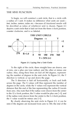
counter clockwise, and is so labeled.
Figure 2-1. Laying Out a Unit Circle
To the right of the circle, three straight lines are drawn, one
at zero, one a plus one (one radius), and the other at minus one
radius. Also, along these lines are laid off 360 degrees, represent-
ing the number of degrees in the unit circle. In Figure 2-1, the Y
direction is vertical, or up and down the page.
The X direction is laid off horizontally, or back and forth
across the page. The X values will thus represent the number of
degrees in the circle, while the Y values will represent the vertical
distance that the end of the line representing the radius R travels
from zero. Also note that if the radius were drawn from the center
to the 12 o’clock position, the Y value would be plus one [+1], and
if the radius were drawn from the center to the 6 o’clock position,
the Y value would be minus one [–1].
By closely observing the unit circle in Figure 2-1, it can be
seen if the degrees are increased from zero to 360, the end of the