
Page 36 - Rotating Machinery Pratical Solutions to Unbalance and Misalignment
P. 36
Rotating Machinery: Practical Solutions
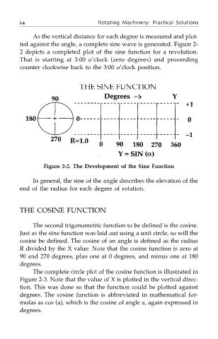
As the vertical distance for each degree is measured and plot-
ted against the angle, a complete sine wave is generated. Figure 2-
2 depicts a completed plot of the sine function for a revolution.
That is starting at 3:00 o’clock (zero degrees) and proceeding
counter clockwise back to the 3:00 o’clock position.
Figure 2-2. The Development of the Sine Function
In general, the sine of the angle describes the elevation of the
end of the radius for each degree of rotation.
THE COSINE FUNCTION
The second trigonometric function to be defined is the cosine.
Just as the sine function was laid out using a unit circle, so will the
cosine be defined. The cosine of an angle is defined as the radius
R divided by the X value. Note that the cosine function is zero at
90 and 270 degrees, plus one at 0 degrees, and minus one at 180
degrees.
The complete circle plot of the cosine function is illustrated in
Figure 2-3. Note that the value of X is plotted in the vertical direc-
tion. This was done so that the function could be plotted against
degrees. The cosine function is abbreviated in mathematical for-
mulas as cos (a), which is the cosine of angle a, again expressed in
degrees.