
Page 60 - Rotating Machinery Pratical Solutions to Unbalance and Misalignment
P. 60
Rotating Machinery: Practical Solutions
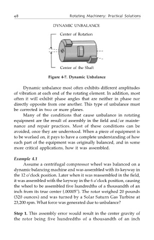
DYNAMIC UNBALANCE
Center of Rotation
Center of the Shaft
Figure 4-7. Dynamic Unbalance
Dynamic unbalance most often exhibits different amplitudes
of vibration at each end of the rotating element. In addition, most
often it will exhibit phase angles that are neither in phase nor
directly opposite from one another. This type of unbalance must
be corrected in two or more planes.
Many of the conditions that cause unbalance in rotating
equipment are the result of assembly in the field and/or mainte-
nance and repair practices. Most of these conditions can be
avoided, once they are understood. When a piece of equipment is
to be worked on, it pays to have a complete understanding of how
each part of the equipment was originally balanced, and in some
more critical applications, how it was assembled.
Example 4.1
Assume a centrifugal compressor wheel was balanced on a
dynamic balancing machine and was assembled with its keyway in
the 12 o’clock position. Later when it was reassembled in the field,
it was assembled with the keyway in the 6 o’clock position, causing
the wheel to be assembled five hundredths of a thousandth of an
inch from its true center (.00005"). The rotor weighed 20 pounds
(320 ounces) and was turned by a Solar Saturn Gas Turbine at
23,200 rpm. What force was generated due to unbalance?
Step 1. This assembly error would result in the center gravity of
the rotor being five hundredths of a thousandth of an inch