
Page 82 - Rotating Machinery Pratical Solutions to Unbalance and Misalignment
P. 82
Rotating Machinery: Practical Solutions
B B’
A A ▼ ▼
Ab’
C
▼
Ac
C’
B
Ac’ ▼
A
▼
C
▼
Ab
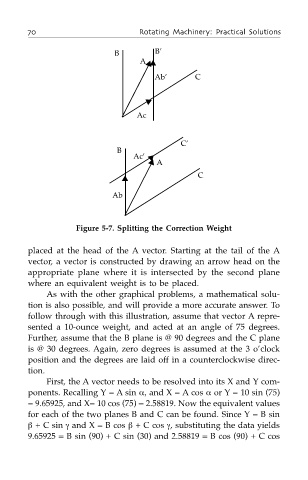
Figure 5-7. Splitting the Correction Weight
placed at the head of the A vector. Starting at the tail of the A
vector, a vector is constructed by drawing an arrow head on the
appropriate plane where it is intersected by the second plane
where an equivalent weight is to be placed.
As with the other graphical problems, a mathematical solu-
tion is also possible, and will provide a more accurate answer. To
follow through with this illustration, assume that vector A repre-
sented a 10-ounce weight, and acted at an angle of 75 degrees.
Further, assume that the B plane is @ 90 degrees and the C plane
is @ 30 degrees. Again, zero degrees is assumed at the 3 o’clock
position and the degrees are laid off in a counterclockwise direc-
tion.
First, the A vector needs to be resolved into its X and Y com-
ponents. Recalling Y = A sin α, and X = A cos α or Y = 10 sin (75)
= 9.65925, and X= 10 cos (75) = 2.58819. Now the equivalent values
for each of the two planes B and C can be found. Since Y = B sin
β + C sin γ and X = B cos β + C cos γ, substituting the data yields
9.65925 = B sin (90) + C sin (30) and 2.58819 = B cos (90) + C cos