
Page 87 - Rotating Machinery Pratical Solutions to Unbalance and Misalignment
P. 87
Field Balancing
These rotating elements will require balancing by a multi-plane
method. This type of balancing is best left to shop balancing and
not attempted in the field.
Multi-plane balancing is beyond the scope of this book and is
not discussed further.
Since this balancing technique requires a bit more accuracy
than the single plane method, it is recommended that a polar
graph be attached to the machine by cutting out the center and
placing it over the end of the shaft. This will assist in determining
the exact phase angles during the balancing process.
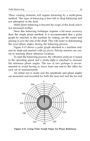
Figure 5-13 shows a polar graph attached to a machine end,
and its shaft end marked with an arrow. Felt-tip markers are use-
ful in marking phase reference locations.
To start the balancing process, the vibration analyzer is tuned
to the operating speed and a strobe light is attached to measure
the reference phase angles. The use of two pickups is recom-
mended to avoid having to move from one end to the other for
each set of measurements.
An initial run is made and the amplitude and phase angles
are measured and recorded for both the near end and the far end
0
330 30
60
300
90
270
240 120
210 150
180
Figure 5-13. Using Polar Graph Paper for Phase Reference