
Page 91 - Rotating Machinery Pratical Solutions to Unbalance and Misalignment
P. 91
Field Balancing
60
90
120
210 150
180
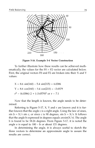
Figure 5-16. Example 5-4 Vector Construction
To further illustrate how these results can be achieved math-
ematically, the values for the F0 > F2 vector are calculated below.
First, the original vectors F0 and F2 are broken into their X and Y
values:
X = 8.6 sin(160) – 5.4 sin(215) = 6.0386
Y = 8.6 cos(160) – 5.4 cos(215) = –3.6579
2
2
r = (6.0386) 2 + (–3.6579) or r = 7.1
Now that the length is known, the angle needs to be deter-
mined.
Referring to Figure 5-17, X, Y and r are known and it is fur-
ther known that the angle c is a right angle. Using the law of sines,
sin b = X/r sin c, or since c is 90 degrees, sin b = X/r. It follows
that the angle b expressed in degrees equals arcsin(X/r). The angle
b is found to be 58.26 degrees. From Figure 5-17, it is noted the
angle e is equal to 180 – b or about 121 degrees.
In determining the angle, it is always useful to sketch the
three vectors to determine an approximate angle to assure the
results are correct.