
Page 89 - Rotating Machinery Pratical Solutions to Unbalance and Misalignment
P. 89
Field Balancing
which it acts. In this case, the vector is drawn from the tip of
the N0 vector to the tip of the N1 vector.
Since vectors have two basic components, their magnitude
and direction, the convention for a vector named A—calculated
from two other vector quantities, X and Y—will be A = (X/Y) units
@ (X + Y) degrees. In this case the desired length is the length of
X divided by Y and the desired angle is X plus Y.
What is important is that the symbol for a vector will repre-
sent its length and the underlined symbol will represent the angle
of that vector.
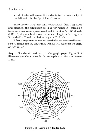
Step 1. Plot the six readings on polar graph paper. Figure 5-14
illustrates the plotted data. In this example, each circle represents
1 mil.
0
330 30
60
300
270 90
240 120
210 150
180
Figure 5-14. Example 5-4 Plotted Data