
Page 90 - Rotating Machinery Pratical Solutions to Unbalance and Misalignment
P. 90
Rotating Machinery: Practical Solutions
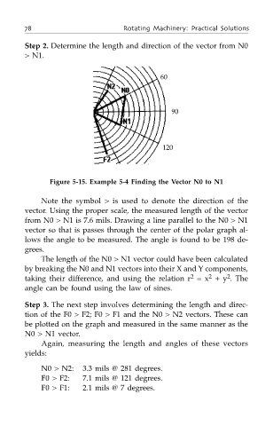
Step 2. Determine the length and direction of the vector from N0
> N1.
60
90
120
Figure 5-15. Example 5-4 Finding the Vector N0 to N1
Note the symbol > is used to denote the direction of the
vector. Using the proper scale, the measured length of the vector
from N0 > N1 is 7.6 mils. Drawing a line parallel to the N0 > N1
vector so that is passes through the center of the polar graph al-
lows the angle to be measured. The angle is found to be 198 de-
grees.
The length of the N0 > N1 vector could have been calculated
by breaking the N0 and N1 vectors into their X and Y components,
2
2
2
taking their difference, and using the relation r = x + y . The
angle can be found using the law of sines.
Step 3. The next step involves determining the length and direc-
tion of the F0 > F2; F0 > F1 and the N0 > N2 vectors. These can
be plotted on the graph and measured in the same manner as the
N0 > N1 vector.
Again, measuring the length and angles of these vectors
yields:
N0 > N2: 3.3 mils @ 281 degrees.
F0 > F2: 7.1 mils @ 121 degrees.
F0 > F1: 2.1 mils @ 7 degrees.