
Page 86 - Rotating Machinery Pratical Solutions to Unbalance and Misalignment
P. 86
Rotating Machinery: Practical Solutions
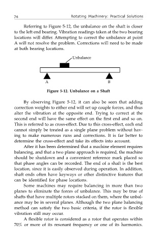
Referring to Figure 5-12, the unbalance on the shaft is closer
to the left end bearing. Vibration readings taken at the two bearing
locations will differ. Attempting to correct the unbalance at point
A will not resolve the problem. Corrections will need to be made
at both bearing locations.
Unbalance
▲ ▲
A B
Figure 5-12. Unbalance on a Shaft
By observing Figure 5-12, it can also be seen that adding
correction weights to either end will set up couple forces, and thus
alter the vibration at the opposite end. Trying to correct at the
second end will have the same effect on the first end and so on.
This is referred to as cross-effect. Due to this cross-effect, each end
cannot simply be treated as a single plane problem without hav-
ing to make numerous runs and corrections. It is far better to
determine the cross-effect and take its effects into account.
After it has been determined that a machine element requires
balancing, and that a two plane approach is required, the machine
should be shutdown and a convenient reference mark placed so
that phase angles can be recorded. The end of a shaft is the best
location, since it is easily observed during operation. In addition,
shaft ends often have keyways or other distinctive features that
can be identified for phase locations.
Some machines may require balancing in more than two
planes to eliminate the forces of unbalance. This may be true of
shafts that have multiple rotors stacked on them, where the unbal-
ance may be in several planes. Although the two plane balancing
method can satisfy the two basic criteria, if the rotor is flexible
vibration still may occur.
A flexible rotor is considered as a rotor that operates within
70% or more of its resonant frequency or one of its harmonics.