
Page 191 - Satellite Communications, Fourth Edition
P. 191
Antennas 171
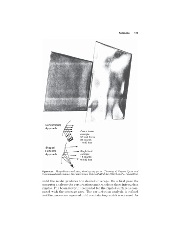
Conventional
Approach
Conus beam
example:
56 feed horns
84 pounds
1.0 dB loss
Shaped
Reflector Single feed
Approach example:
14 pounds
0.3 dB loss
Figure 6.25 Shaped-beam reflector, showing ray paths. (Courtesy of Hughes Space and
Communications Company. Reproduced from Vectors XXXV(3):14, 1993. © Hughes Aircraft Co.)
until the model produces the desired coverage. On a first pass the
computer analyzes the perturbations and translates these into surface
ripples. The beam footprint computed for the rippled surface is com-
pared with the coverage area. The perturbation analysis is refined
and the passes are repeated until a satisfactory match is obtained. As