Page 194 - Satellite Communications, Fourth Edition
P. 194

174  Chapter Six

                               (Imaginary)
                                 j


                                                   E  ψ
                                          E R
                                              E
                                       E        ψ
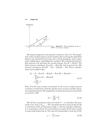
                                                                 Figure 6.27 Phasor diagram for the in-
                                 0                         (Real) line array of dipoles.


                                The Argand diagram for the phasors is shown in Fig. 6.27. The magni-
                              tude of the resultant phasor can be found by first resolving the individual
                              phasors into horizontal (real axis) and vertical (imaginary axis) compo-
                              nents, adding these, and finding the resultant. The contribution from the
                              first element is E, and from the second element, E cos    jE sin   . The
                              third element contributes E cos 2   jE sin 2  , and in general the Nth
                              element contributes E cos(N   1)   jE sin(N   1)  . These contribu-
                              tions can be added to get:

                                        E   E cos    jE sin    E cos 2   jE sin 2    c
                                   E R
                                        N 1
                                           a  E cos n   jE sin n
                                         n 0                                             (6.37)
                                          N 1
                                              jn
                                        E  a e
                                          n 0
                              Here, N is the total number of elements in the array. A single element
                              would have resulted in a field E, and the array is seen to modify this by
                              the summation factor. The magnitude of summation factor is termed the
                              array factor (AF):
                                                              N 1
                                                       AF   2  a e  jn  2                (6.38)
                                                              n 0
                                The AF has a maximum value of N when    0  , and hence the max-

                              imum value of E is E R max   NE . Recalling that  as given by Eq. (6.36)
                                            R
                              is a function of the current phase angle,  , and the angular coordinate,
                               , it is possible to choose the current phase to make the AF show a peak
                              in some desired direction   . The required relationship is, from Eq. (6.36),
                                                     0
                                                             2
                                                               s cos   0                 (6.39)
                                                             l
   189   190   191   192   193   194   195   196   197   198   199