
Page 198 - Satellite Communications, Fourth Edition
P. 198
Chapter Six
178
178 Chapter Six
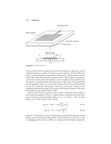
Microstrip feeder
Patch antenna
Dielectric substrate
Ground plane
(a)
Radiated fields
Patch
(b)
Figure 6.29 A patch antenna.
itself, and the feed arrangement, but the principles of operation can be
understood from a study of the basic patch radiator. In Fig. 6.29a the
feed is a microstrip line connecting to the patch, and the copper on the
underside of the board forms a ground plane. The dielectric substrate
is thin (less than about one-tenth of a wavelength) and the field under
the patch is concentrated in the dielectric. At the edges of the patch the
electromagnetic fields are associated with surface waves and radiated
waves, the radiation taking place from the “apertures” formed in the
substrate between the edges of the patch and the ground plane. The radi-
ated fields are sketched in Fig. 6.29b.
Figure 6.30 shows the patch of sides a and b situated at the origin of
the coordinate system of Fig. 6.3. Approximate expressions for the radi-
ation pattern in the principal planes at 0 and 90° are [see
James et al., 1981, Eqs. (4.26a and b)]:
2 b
g(
, 90 ) cos a sin
b (6.41)
l 0
2
g(
, 0) cos
c sin X d (6.42)
2
X
where X ( a/l )sin
, and l is the free space wavelength. Equation (6.42)
0
0
will be seen to be similar to Eq. (6.23). A plot of these functions, for a half
wavelength patch is shown in Fig. 6.31. In practice the length of each side