
Page 196 - Satellite Communications, Fourth Edition
P. 196
176 Chapter Six
For this particular example, the values were purposely chosen to
illustrate what is termed an end-fire array, where the main beam is
directed along the positive axis of the array. Keep in mind that a single
dipole would have had a circular pattern. An example of a 5-element end
fire array is given in Problem 6.32.
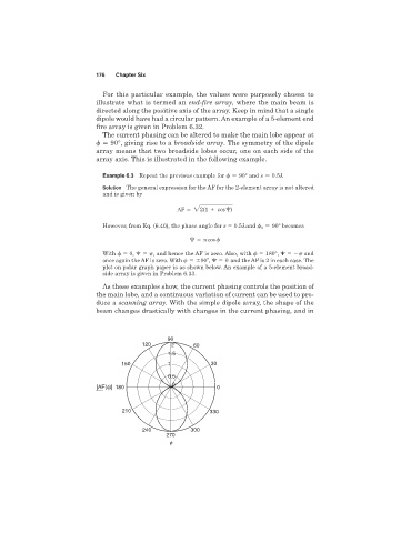
The current phasing can be altered to make the main lobe appear at
90°, giving rise to a broadside array. The symmetry of the dipole
array means that two broadside lobes occur, one on each side of the
array axis. This is illustrated in the following example.
Example 6.3 Repeat the previous example for 90° and s 0.5l
Solution The general expression for the AF for the 2-element array is not altered
and is given by
AF 22(1 cos )
However, from Eq. (6.40), the phase angle for s 0.5l and 0 90° becomes
cos
With 0, , and hence the AF is zero. Also, with 180°, and
o
once again the AF is zero. With 90 , 0 and the AF is 2 in each case. The
plot on polar graph paper is as shown below. An example of a 5-element broad-
side array is given in Problem 6.33.
As these examples show, the current phasing controls the position of
the main lobe, and a continuous variation of current can be used to pro-
duce a scanning array. With the simple dipole array, the shape of the
beam changes drastically with changes in the current phasing, and in
90
120 2 60
1.5
150 1 30
0.5
0
|AF(f)| 180 0
210 330
240 300
270
f