
Page 394 - Satellite Communications, Fourth Edition
P. 394
374 Chapter Twelve
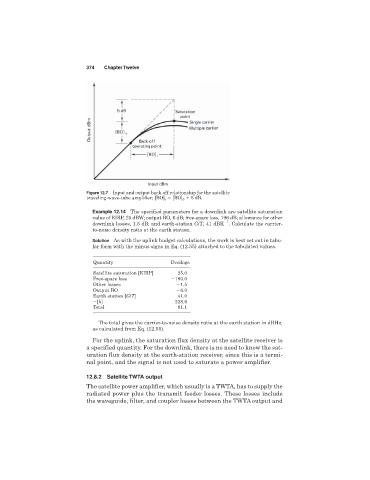
Figure 12.7 Input and output back-off relationship for the satellite
traveling-wave-tube amplifier; [BO] i [BO] 0 5 dB.
Example 12.14 The specified parameters for a downlink are satellite saturation
value of EIRP, 25 dBW; output BO, 6 dB; free-space loss, 196 dB; allowance for other
1
downlink losses, 1.5 dB; and earth-station G/T, 41 dBK . Calculate the carrier-
to-noise density ratio at the earth station.
Solution As with the uplink budget calculations, the work is best set out in tabu-
lar form with the minus signs in Eq. (12.55) attached to the tabulated values.
Quantity Decilogs
Satellite saturation [EIRP] 25.0
Free-space loss 196.0
Other losses 1.5
Output BO 6.0
Earth station [G/T] 41.0
[k] 228.6
Total 91.1
The total gives the carrier-to-noise density ratio at the earth station in dBHz,
as calculated from Eq. (12.55).
For the uplink, the saturation flux density at the satellite receiver is
a specified quantity. For the downlink, there is no need to know the sat-
uration flux density at the earth-station receiver, since this is a termi-
nal point, and the signal is not used to saturate a power amplifier.
12.8.2 Satellite TWTA output
The satellite power amplifier, which usually is a TWTA, has to supply the
radiated power plus the transmit feeder losses. These losses include
the waveguide, filter, and coupler losses between the TWTA output and