
Page 409 - Satellite Communications, Fourth Edition
P. 409
The Space Link 389
The [EIRP] is
[EIRP] [P T ] [G T ] [AML] T [TFL]
5.3 36.7 1.8 1.8
38.4 dBW
The total losses, including the link margin and the receiver misalignment (point-
ing) loss are:
[LOSSES] 192.6 1.8 1.8 196.2 dB. The received power is, from Eq. (12.13)
[P R ] [EIRP] [G R ] [LOSSES]
121.1 dBW
Radio ISLs have the advantage that the technology is mature, so the
risk of failure is minimized. However, the bandwidth limits the bit rate
that can be carried, and optical systems, with their much higher carrier
(optical) frequencies, have much greater bandwidth. Optical ISLs have
a definite advantage over rf ISLs for data rates in excess of about 1 Gbps
Also, telescope apertures are used which are considerably smaller than
their rf counterparts, and generally, optical equipment tends to be smaller
and more compact (see Optical Communications and IntersatelliteLinks,
undated, at www.wtec.org/loyola/satcom2/03_06.htm-22k-). The optical
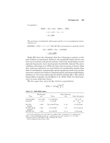
beamwidth is typically 5 rad (Maral et al., 2002). Table 12.5 lists prop-
erties of some solid state lasers.
The free-space loss given by Eq. (12.9) is repeated here:
2
[FSL] 10 loga 4 r b
l
TABLE 12.5 Solid State Lasers
Wavelength, Beam diameter,
Type m Power mm Beam divergence
GaAs/GaAlAs 0.78–0.905 1–40 mW Avg 10° 35°
InGaAsP 1.1–1.6 1–10 mW 10° 30° 20°
40°
Nd: YAG 1.064 Up to 600 W Avg 1– 10 0.3–20 mrad
Pulsed
Nd:YAG Diode 1.064 0.5–10 mW 1–2 0.5–2.0 mrad
pumped
Nd:YAG (cw) 1.064 0.04–600 W 0.7–8 2–25 mrad
NOTES: Al—aluminum; As—arsenide; Ga—gallium; Nd—neodymium; P— phosphorus;
YAG—yttrium-aluminum garnet; cw—continuous wave; m—micron = 10 6 m; mm—
millimeter; mrad—milliradian; mW—milliwatt; W—watt.
SOURCE: Extracted from Chen, 1996.