
Page 406 - Satellite Communications, Fourth Edition
P. 406
386 Chapter Twelve
ground stations. Although many different links are possible, the most
useful ones in operation are:
■ low earth orbiting (LEO) satellites—LEO ↔ LEO
■ geostationary earth orbiting (GEO) satellites—GEO ↔ GEO
■ LEO ↔ GEO
Consider first some of the applications to GEOs. As shown in Chap.
3, the antenna angle of elevation is limited to a minimum of about 5
degrees because of noise induced from the earth. The limit of visibility
as set by the minimum angle of elevation is a function of the satellite
longitude and earth-station latitude and longitude as shown in Sec. 3.2.
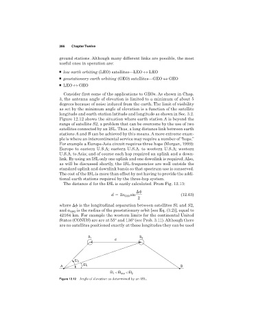
Figure 12.12 shows the situation where earth station A is beyond the
range of satellite S2, a problem that can be overcome by the use of two
satellites connected by an ISL. Thus, a long distance link between earth
stations A and B can be achieved by this means. A more extreme exam-
ple is where an intercontinental service may require a number of “hops.”
For example a Europe-Asia circuit requires three hops (Morgan, 1999):
Europe to eastern U.S.A; eastern U.S.A. to western U.S.A; western
U.S.A. to Asia; and of course each hop required an uplink and a down-
link. By using an ISL only one uplink and one downlink is required. Also,
as will be discussed shortly, the ISL frequencies are well outside the
standard uplink and downlink bands so that spectrum use is conserved.
The cost of the ISL is more than offset by not having to provide the addi-
tional earth stations required by the three-hop system.
The distance d for the ISL is easily calculated. From Fig. 12.13:
d 2a GSO sin (12.63)
2
where is the longitudinal separation between satellites S1 and S2,
and a GSO is the radius of the geostationary orbit [see Eq. (3.2)], equal to
42164 km. For example the western limits for the continental United
States (CONUS) arc are at 55° and 136°(see Prob. 3.11). Although there
are no satellites positioned exactly at these longitudes they can be used
S 1 S 2
d
El 2
El
A 1 B
El < El min < El 2
1
Figure 12.12 Angle of elevation as determined by an ISL.