
Page 403 - Satellite Communications, Fourth Edition
P. 403
The Space Link 383
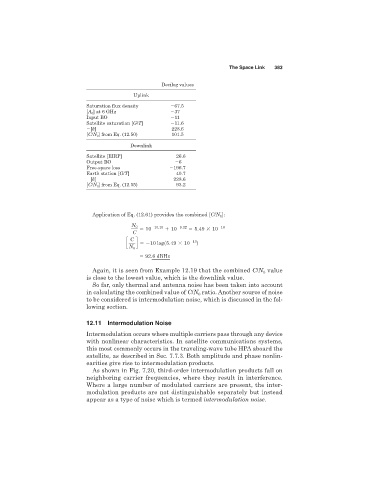
Decilog values
Uplink
Saturation flux density 67.5
[A 0 ] at 6 GHz 37
Input BO 11
Satellite saturation [G/T] 11.6
[k] 228.6
[C/N 0 ] from Eq. (12.50) 101.5
Downlink
Satellite [EIRP] 26.6
Output BO 6
Free-space loss 196.7
Earth station [G/T] 40.7
[k] 228.6
[C/N 0 ] from Eq. (12.55) 93.2
Application of Eq. (12.61) provides the combined [C/N 0 ]:
N 0 210.15 29.32 210
5 10 1 10 5 5.49 3 10
C
c C d 5210 logs5.49 3 10 210 d
N 0
92.6 dBHz
Again, it is seen from Example 12.19 that the combined C/N value
0
is close to the lowest value, which is the downlink value.
So far, only thermal and antenna noise has been taken into account
in calculating the combined value of C/N ratio. Another source of noise
0
to be considered is intermodulation noise, which is discussed in the fol-
lowing section.
12.11 Intermodulation Noise
Intermodulation occurs where multiple carriers pass through any device
with nonlinear characteristics. In satellite communications systems,
this most commonly occurs in the traveling-wave tube HPA aboard the
satellite, as described in Sec. 7.7.3. Both amplitude and phase nonlin-
earities give rise to intermodulation products.
As shown in Fig. 7.20, third-order intermodulation products fall on
neighboring carrier frequencies, where they result in interference.
Where a large number of modulated carriers are present, the inter-
modulation products are not distinguishable separately but instead
appear as a type of noise which is termed intermodulation noise.