
Page 423 - Satellite Communications, Fourth Edition
P. 423
Interference 403
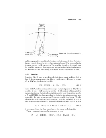
Figure 13.3 Orbital spacing angle.
and the equatorial arc subtended by this angle is about 314 km. In inter-
ference calculations, therefore, the earth stations will be assumed to be
situated on the 3-dB contours of the satellite footprints, in which case
the satellite antennas do not provide any gain discrimination between
the wanted and the interfering carriers on either transmit or receive.
13.2.1 Downlink
Equation (12.13) may be used to calculate the wanted and interfering
downlink carrier powers received by an earth station. The carrier power
[C] in dBW received at station B is
[C] [EIRP] 3 [G ] [FSL] (13.1)
1
B
Here, [EIRP] is the equivalent isotropic radiated power in dBW from
1
satellite 1, the 3 dB accounts for the 3-dB contour of the satellite
is the boresight (on-axis) receiving antenna gain
transmit antenna, G B
at B, and [FSL] is the free-space loss in decibels. A similar equation may
be used for the interfering carrier [I], except an additional term [Y] dB,
D
allowing for polarization discrimination, must be included. Also, the
receiving antenna gain at B is determined by the off-axis angle
, giving
[I ] [EIRP] 3 [G (
)] [FSL] [Y ] D (13.2)
B
2
It is assumed that the free-space loss is the same for both paths.
These two equations may be combined to give
1
[C] [I ] [EIRP] [EIRP] 2 [G B ] [G B (
)] [Y ] D