
Page 428 - Satellite Communications, Fourth Edition
P. 428
408 Chapter Thirteen
Typical [Q] values obtained from the FCC report are as follows: with the
wanted carrier a TV/FM signal and the interfering carrier a similar
TV/FM signal, [Q] 0 dB; with SCPC/PSK interfering carriers, [Q]
27.92 dB; and with the interfering carrier a wideband digital-type signal,
[Q] 3.36 dB.
The passband [C/I] ratio is calculated using
c C d c C d [Q] (13.7)
I pb I ant
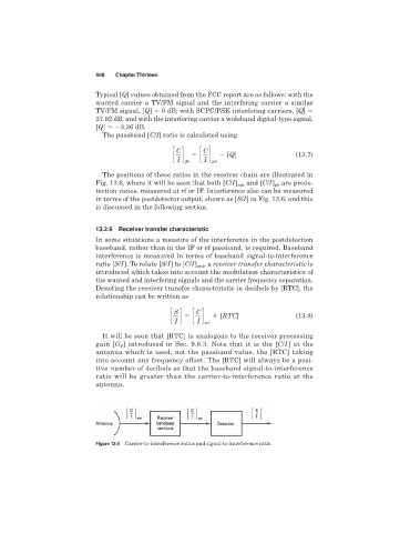
The positions of these ratios in the receiver chain are illustrated in
and [C/I] are prede-
Fig. 13.6, where it will be seen that both [C/I] ant pb
tection ratios, measured at rf or IF. Interference also can be measured
in terms of the postdetector output, shown as [S/I] in Fig. 13.6, and this
is discussed in the following section.
13.2.6 Receiver transfer characteristic
In some situations a measure of the interference in the postdetection
baseband, rather than in the IF or rf passband, is required. Baseband
interference is measured in terms of baseband signal-to-interference
ratio [S/I]. To relate [S/I] to [C/I] ant , a receiver transfer characteristic is
introduced which takes into account the modulation characteristics of
the wanted and interfering signals and the carrier frequency separation.
Denoting the receiver transfer characteristic in decibels by [RTC], the
relationship can be written as
S
c d c C d [RTC] (13.8)
I I ant
It will be seen that [RTC] is analogous to the receiver processing
gain [G ] introduced in Sec. 9.6.3. Note that it is the [C/I] at the
P
antenna which is used, not the passband value, the [RTC] taking
into account any frequency offset. The [RTC] will always be a posi-
tive number of decibels so that the baseband signal-to-interference
ratio will be greater than the carrier-to-interference ratio at the
antenna.
Figure 13.6 Carrier-to-interference ratios and signal-to-interference ratio.