
Page 431 - Satellite Communications, Fourth Edition
P. 431
Interference 411
It should be noted that the receiver transfer characteristic discussed
in Sec. 13.2.6 was developed from the CCIR protection ratio concept
(see Jeruchim and Kane, 1970).
13.3 Energy Dispersal
The power in a frequency-modulated signal remains constant, inde-
pendent of the modulation index. When unmodulated, all the power is
at the carrier frequency, and when modulated, the same total power is
distributed among the carrier and the sidebands. At low modulation
indices the sidebands are grouped close to the carrier, and the power
spectral density, or wattage per unit bandwidth, is relatively high in that
spectral region. At high modulation indices, the spectrum becomes
widely spread, and the power spectral density relatively low.
Use is made of this property in certain situations to keep radiation
within CCIR recommended limits. For example, to limit the A mode of
2
interference in the 1- to 15-GHz range for the fixed satellite service,
CCIR Radio Regulations state, in part, that the earth station EIRP
should not exceed 40 dBW in any 4-kHz band for 0 and should not
exceed 40 3 dBW in any 4-kHz band for 0 5 . The angle
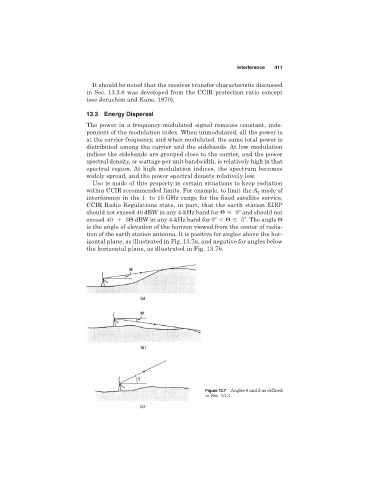
is the angle of elevation of the horizon viewed from the center of radia-
tion of the earth station antenna. It is positive for angles above the hor-
izontal plane, as illustrated in Fig. 13.7a, and negative for angles below
the horizontal plane, as illustrated in Fig. 13.7b.
Figure 13.7 Angles
and as defined
in Sec. 13.3.