
Page 434 - Satellite Communications, Fourth Edition
P. 434
414 Chapter Thirteen
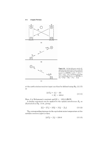
Figure 13.8 (a) Interference modes B 1
and B 2 from network R′ into network
R.(b) For the B 1 mode the interfering
power in dBW/Hz is [I 1 ] [U S ]
[G′ S ] [G E ] [L D ]. (c) For the B 2 mode
the interfering power in dBW/Hz is
[I 2 ] [U E ] [G′ E ] [G S ] [L U ].
at the earth-station receiver input can then be defined using Eq. (12.15)
as
] [I ] [k]
[ T E 1
(13.11)
[I ] 228.6
1
Here, k is Boltzmann’s constant and [k] 228.6 dBJ/K.
A similar argument can be applied to the uplink interference B , as
2
illustrated in Fig. 13.8c, giving
[I ] [U ] [G′ ] [G ] [L ] (13.12)
S
U
2
E
E
The corresponding increase in the equivalent noise temperature at the
satellite receiver input is then
[ T ] [I 2 ] 228.6 (13.13)
S