
Page 458 - Satellite Communications, Fourth Edition
P. 458
438 Chapter Fourteen
This is also referred to as the burst rate, but note that this means the
instantaneous bit rate within a burst (not the number of bursts per
second, which is simply equal to 1/T ). It will be seen that the average
B
bit rate for the burst mode is simply M/T , which is equal to the input
F
and output rates.
The frame time T will be seen to add to the overall propagation
F
delay. For example, in the simple system illustrated in Fig. 14.11, even
if the actual propagation delay between transmit and receive buffers
is assumed to be zero, the receiving side would still have to wait a time
T before receiving the first transmitted burst. In a geostationary
F
satellite system, the actual propagation delay is a significant fraction
of a second, and excessive delays from other causes must be avoided.
This sets an upper limit to the frame time, although with current tech-
nology other factors restrict the frame time to well below this limit. The
frame period is usually chosen to be a multiple of 125 s, which is the
standard sampling period used in pulse-code modulation (PCM) teleph-
ony systems, since this ensures that the PCM samples can be distrib-
uted across successive frames at the PCM sampling rate.
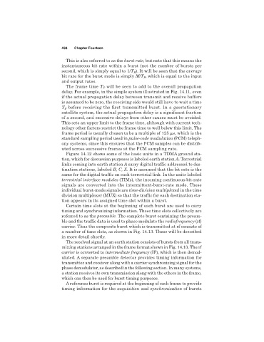
Figure 14.12 shows some of the basic units in a TDMA ground sta-
tion, which for discussion purposes is labeled earth station A. Terrestrial
links coming into earth station A carry digital traffic addressed to des-
tination stations, labeled B, C, X. It is assumed that the bit rate is the
same for the digital traffic on each terrestrial link. In the units labeled
terrestrial interface modules (TIMs), the incoming continuous-bit-rate
signals are converted into the intermittent-burst-rate mode. These
individual burst-mode signals are time-division multiplexed in the time
division multiplexer (MUX) so that the traffic for each destination sta-
tion appears in its assigned time slot within a burst.
Certain time slots at the beginning of each burst are used to carry
timing and synchronizing information. These time slots collectively are
referred to as the preamble. The complete burst containing the pream-
ble and the traffic data is used to phase modulate the radiofrequency (rf)
carrier. Thus the composite burst which is transmitted at rf consists of
a number of time slots, as shown in Fig. 14.13. These will be described
in more detail shortly.
The received signal at an earth station consists of bursts from all trans-
mitting stations arranged in the frame format shown in Fig. 14.13. The rf
carrier is converted to intermediate frequency (IF), which is then demod-
ulated. A separate preamble detector provides timing information for
transmitter and receiver along with a carrier synchronizing signal for the
phase demodulator, as described in the following section. In many systems,
a station receives its own transmission along with the others in the frame,
which can then be used for burst-timing purposes.
A reference burst is required at the beginning of each frame to provide
timing information for the acquisition and synchronization of bursts