
Page 463 - Satellite Communications, Fourth Edition
P. 463
Satellite Access 443
14.7.3 Carrier recovery
A factor, which must be taken into account with TDMA is that the var-
ious bursts in a frame lack coherence so that carrier recovery must be
repeated for each burst. This applies to the traffic as well as the refer-
ence bursts. Where the carrier recovery circuit employs a phase-locked
loop such as shown in Fig. 10.20, a problem known as hangup can occur.
This arises when the loop moves to an unstable region of its operating
characteristic. The loop operation is such that it eventually returns to
a stable operating point, but the time required to do this may be unac-
ceptably long for burst-type signals.
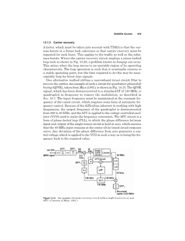
One alternative method utilizes a narrowband tuned circuit filter to
recover the carrier. An example of such a circuit for quadrature phaseshift
keying (QPSK), taken from Miya (1981), is shown in Fig. 14.15. The QPSK
signal, which has been downconverted to a standard IF of 140 MHz, is
quadrupled in frequency to remove the modulation, as described in
Sec. 10.7. The input frequency must be maintained at the resonant fre-
quency of the tuned circuit, which requires some form of automatic fre-
quency control. Because of the difficulties inherent in working with high
frequencies, the output frequency of the quadrupler is downconverted
from 560 to 40 MHz, and the AFC is applied to the voltage controlled oscil-
lator (VCO) used to make the frequency conversion. The AFC circuit is a
form of phase-locked loop (PLL), in which the phase difference between
input and output of the single-tuned circuit is held at zero, which ensures
that the 40-MHz input remains at the center of the tuned circuit response
curve. Any deviation of the phase difference from zero generates a con-
trol voltage which is applied to the VCO in such a way as to bring the fre-
quency back to the required value.
Figure 14.15 An example of carrier recovery circuit with a single-tuned circuit and
AFC. (Courtesy of Miya, 1981.)