
Page 368 - Schaum's Outline of Theory and Problems of Applied Physics
P. 368
CHAP. 29] ALTERNATING-CURRENT CIRCUITS 353
SOLVED PROBLEM 29.6
The reactance of an inductor is 80 at 500 Hz. Find its inductance.
Since X L = 2π f L,
X L 80
L = = = 0.0255 H = 25.5mH
2π f (2π)(500 Hz)
PHASE ANGLE
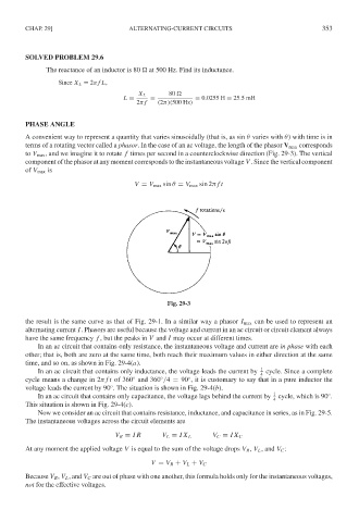
A convenient way to represent a quantity that varies sinusoidally (that is, as sin θ varies with θ) with time is in
terms of a rotating vector called a phasor. In the case of an ac voltage, the length of the phasor V max corresponds
to V max , and we imagine it to rotate f times per second in a counterclockwise direction (Fig. 29-3). The vertical
component of the phasor at any moment corresponds to the instantaneous voltage V . Since the vertical component
of V max is
V = V max sin θ = V max sin 2π ft
Fig. 29-3
the result is the same curve as that of Fig. 29-1. In a similar way a phasor I max can be used to represent an
alternating current I. Phasors are useful because the voltage and current in an ac circuit or circuit element always
have the same frequency f , but the peaks in V and I may occur at different times.
In an ac circuit that contains only resistance, the instantaneous voltage and current are in phase with each
other; that is, both are zero at the same time, both reach their maximum values in either direction at the same
time, and so on, as shown in Fig. 29-4(a).
In an ac circuit that contains only inductance, the voltage leads the current by 1 cycle. Since a complete
4
◦
cycle means a change in 2π ft of 360 and 360 /4 = 90 , it is customary to say that in a pure inductor the
◦
◦
voltage leads the current by 90 . The situation is shown in Fig. 29-4(b).
◦
In an ac circuit that contains only capacitance, the voltage lags behind the current by 1 cycle, which is 90 .
◦
4
This situation is shown in Fig. 29-4(c).
Now we consider an ac circuit that contains resistance, inductance, and capacitance in series, as in Fig. 29-5.
The instantaneous voltages across the circuit elements are
V R = IR V L = IX L V C = IX C
At any moment the applied voltage V is equal to the sum of the voltage drops V R , V L , and V C :
V = V R + V L + V C
Because V R , V L , and V C are out of phase with one another, this formula holds only for the instantaneous voltages,
not for the effective voltages.