
Page 85 - Semiconductor For Micro- and Nanotechnology An Introduction For Engineers
P. 85
The Crystal Lattice System
111]
[ (a) [ 001] (b) [ 001]
Quasi-
longitudinal P [ 010]
wave
[ 010]
[ 100]
Shear Quasi-shear
polarization S wave S wave
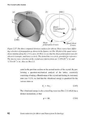
Figure 2.27. The three computed slowness surfaces for silicon. These waves have differ-
ing velocities of propagation as shown in the figures. (a) The 3D plot of the quasi waves
shows minima along the 111[ ] axes. (b) Here we see that the shear polarization wave for
silicon is isotropic, and hence a circle. The dotted line is a circle, provided for reference.
4
–
The inverse wave velocities at the crystal axes intersections are 1.119×10 sm⁄ and
– 4
⁄
1.711×10 sm . Also see Box 2.5.
cated in the previous section on the normal modes of the crystal. By per-
forming a quantum-mechanical analysis of the lattice, essentially
consisting of taking a Hamiltonian of the crystal and finding its stationary
state (see 3.2.5), we find that the vibrational energy is quantized for the
various states as
E = —ω j . (2.83)
j
The vibrational energy is also a travelling wave (see Box 2.1) which has a
distinct momentum, so that
p = —k . (2.84)
82 Semiconductors for Micro and Nanosystem Technology