
Page 232 - Sensing, Intelligence, Motion : How Robots and Humans Move in an Unstructured World
P. 232
PLANAR REVOLUTE–REVOLUTE (RR) ARM 207
happen in scenes with obstacles of certain shapes and with certain mutual posi-
tions of obstacles and start and target points. The procedure that we are about to
formulate for the RR arm motion planning can create local cycles as well. As
for mobile robots, local cycles do not affect convergence of the RR arm plan-
ning algorithm, but they do result in longer paths. For the process to work, the
algorithm does not need to recognize those local cycles or undertake any specific
action when they occur.
A local cycle is created when the arm image point on the C-space torus comes
back to a previously defined hit point, and the contents of its counters C i at this
moment is different from n i · 2π, |n i |= 0, 1, 2,... ,i = 1, 2. This may occur
only if between two consecutive encounters of the same hit point the arm has
defined other hit point(s). (Recall that the counters C i are turned on when a hit
point is defined.) Otherwise the contents of C i would be exactly n i · 2π.
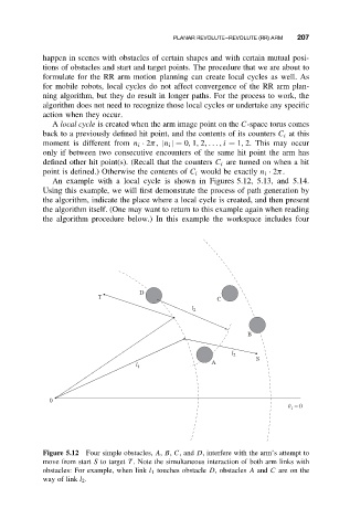
An example with a local cycle is shown in Figures 5.12, 5.13, and 5.14.
Using this example, we will first demonstrate the process of path generation by
the algorithm, indicate the place where a local cycle is created, and then present
the algorithm itself. (One may want to return to this example again when reading
the algorithm procedure below.) In this example the workspace includes four
D
T C
l 2
B
l 2
S
A
l 1
0
q 1 = 0
Figure 5.12 Four simple obstacles, A, B, C,and D, interfere with the arm’s attempt to
move from start S to target T . Note the simultaneous interaction of both arm links with
obstacles: For example, when link l 1 touches obstacle D, obstacles A and C are on the
way of link l 2 .