
Page 313 - Sensing, Intelligence, Motion : How Robots and Humans Move in an Unstructured World
P. 313
288 MOTION PLANNING FOR THREE-DIMENSIONAL ARM MANIPULATORS
l 3
O
T
L
M-plane b
a
H
o b′ L′ T′ l
S 2
a′
S′ H′
l 1
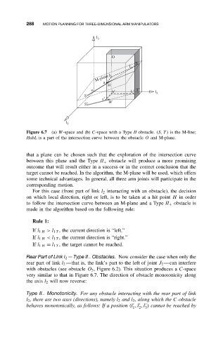
Figure 6.7 (a) W-space and (b) C-space with a Type II obstacle. (S, T ) is the M-line;
HabL is a part of the intersection curve between the obstacle O and M-plane.
that a plane can be chosen such that the exploration of the intersection curve
between this plane and the Type II + obstacle will produce a more promising
outcome that will result either in a success or in the correct conclusion that the
target cannot be reached. In the algorithm, the M-plane will be used, which offers
some technical advantages. In general, all three arm joints will participate in the
corresponding motion.
For this case (front part of link l 2 interacting with an obstacle), the decision
on which local direction, right or left, is to be taken at a hit point H in order
to follow the intersection curve between an M-plane and a Type II + obstacle is
made in the algorithm based on the following rule:
Rule 1:
If l 1 H >l 1 T , the current direction is “left.”
If l 1 H <l 1 T , the current direction is “right.”
If l 1 H = l 1 T , the target cannot be reached.
Rear Part of Link l 2 —Type II − Obstacles. Now consider the case when only the
rear part of link l 2 —that is, the link’s part to the left of joint J 2 —can interfere
with obstacles (see obstacle O 3 , Figure 6.2). This situation produces a C-space
very similar to that in Figure 6.7. The direction of obstacle monotonicity along
the axis l 2 will now reverse:
Type II − Monotonicity. For any obstacle interacting with the rear part of link
l 2 , there are two axes (directions), namely l 2 and l 3 , along which the C-obstacle
behaves monotonically, as follows: If a position (l ,l ,l ) cannot be reached by
1 2 3