
Page 111 - Sensors and Control Systems in Manufacturing
P. 111
72
T w o
Cha p te r
FIGURE 2.56 D
Lateral approach— Recommended
recommended sensing area
sensing distance. Target 0.75 × D
should not be used. That is the point where sensing range variations
start to occur. Therefore, it is recommended that the target pass not
more than 75 percent of the sensing distance D from the sensor face.
Also, the target should not pass any closer than the basic tolerance
incorporated in the machine design in order to prevent damage to the
sensor. Hysteresis can be greater for an axial approach (Fig. 2.56).
2.6.6 Variation Between Devices
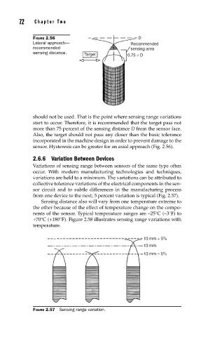
Variations of sensing range between sensors of the same type often
occur. With modern manufacturing technologies and techniques,
variations are held to a minimum. The variations can be attributed to
collective tolerance variations of the electrical components in the sen-
sor circuit and to subtle differences in the manufacturing process
from one device to the next; 5 percent variation is typical (Fig. 2.57).
Sensing distance also will vary from one temperature extreme to
the other because of the effect of temperature change on the compo-
nents of the sensor. Typical temperature ranges are –25°C (–3°F) to
+70°C (+180°F). Figure 2.58 illustrates sensing range variations with
temperature.
13 mm + 5%
13 mm
13 mm – 5%
FIGURE 2.57 Sensing range variation.