
Page 110 - Sensors and Control Systems in Manufacturing
P. 110
Classification and Types of Sensors
Tubular, mm 71
Limit-Switch Pancake
Target Material Type Type 8 12 18 30
Steel (1020) 1.0 1.0 1.0 1.0 1.0 1.0
Stainless steel (400) 1.03 0.90 0.90 0.90 1.0 1.0
Stainless steel (300) 0.85 0.70 0.60 0.70 0.70 0.65
Brass 0.50 0.54 0.35 0.45 0.45 0.45
Aluminum 0.47 0.50 0.35 0.40 0.45 0.40
Copper 0.40 0.46 0.30 0.25 0.35 0.30
TABLE 2.6 Target Correction
2.6.5 Target Shape
Standard targets are assumed to be a flat square shape with the stated
dimensions. Targets of round shape or with a pocketed surface must
be of adequate dimensions to cause the necessary dampening effect
on the sensor. Allowing the sensor-to-target distance less than the
nominal range will help assure proper sensing. Also, using the next
larger size or an extended-range sensor will help minimize problems
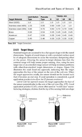
with other-than-standard target dimensions or shapes. Figure 2.54
illustrates the axial (head-on) approach, indicating that the target
approaches the face of the sensor on the axis of the coil core. When
the target approaches axially, the sensor should not be located such
that it becomes an end stop. If axial operation is considered, a good
application practice is to allow for 25 percent overtravel.
Lateral (side by) approach means the target approaches the face of
the sensor perpendicular to the axis of the coil core (Fig. 2.55). Good
application practice (GAP), a term often used in “world-class” manu-
facturing strategies, dictates that the tip of the sensing field envelope
Target Reference
axis
Reference Target
axis
FIGURE 2.54 Axial FIGURE 2.55 Lateral
approach. approach.