
Page 105 - Sensors and Control Systems in Manufacturing
P. 105
66
Target Cha p te r T w o
Sensor
Oscillator
circuit
output
Wave Operating level Releasing level
detecting
circuit output
ON
Output OFF OFF
circuit
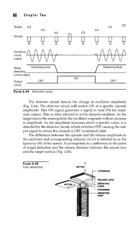
FIGURE 2.44 Detection cycle.
The detector circuit detects the change in oscillator amplitude
(Fig. 2.44). The detector circuit will switch ON at a specific operate
amplitude. This ON signal generates a signal to turn ON the solid-
state output. This is often referred to as the damped condition. As the
target leaves the sensing field, the oscillator responds with an increase
in amplitude. As the amplitude increases above a specific value, it is
detected by the detector circuit, which switches OFF, causing the out-
put signal to return the normal or OFF (undamped) state.
The difference between the operate and the release amplitude in
the oscillator and corresponding detector circuit is referred to as the
hysteresis (H) of the sensor. It corresponds to a difference in the point
of target detection and the release distance between the sensor face
and the target surface (Fig. 2.45).
FIGURE 2.45
Core assembly.