
Page 119 - Sensors and Control Systems in Manufacturing
P. 119
80
Cha p te r
T w o
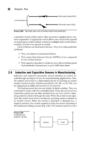
[Normally closed (NC)]
Limit switches
[Normally open (NO)]
FIGURE 2.65 Normally open and normally closed microswitches.
a normally closed switch opens when pressure is applied and a con-
tact is separated. A single-pole switch allows one circuit to be opened
or closed upon switch contact, whereas a multiple-pole switch allows
multiple circuits to be opened or closed.
Limit switches are mechanical devices. They have three potential
problems:
• They are subject to mechanical failure.
• Their mean time between failures (MTBFs) is low compared
to non-contact sensors.
• Their speed of operation is relatively slow; the switching speed
of photoelectric microsensors is up to 3000 times faster.
2.9 Inductive and Capacitive Sensors in Manufacturing
Inductive and capacitive proximity sensors interface to control cir-
cuits through an output circuit, for manufacturing applications. Also,
the control circuit type is a determining factor in choosing an output
circuit. Control circuits, whether powered by AC, DC, or AC/DC, can
be categorized as either load powered or line powered.
The load-powered devices are similar to limit switches. They are
connected in series with the controlled load. These devices have two
connection points and are often referred to as two-wire switches. Oper-
ating current is drawn through the load. When the switch is not oper-
ated, the switch must draw a minimum operating current referred to
as residual current. When the switch is operated or damped (i.e., a
target is present), the current required to keep the sensor operating is
the minimum holding current (Fig. 2.66). The residual current is not a
FIGURE 2.66
Load-powered
residual current.
Sensor Load