
Page 122 - Sensors and Control Systems in Manufacturing
P. 122
Classification and Types of Sensors
60 Hz 1 cycle = 16.66 ms 83
1 cycle 0.5 cycle = 8.33 ms
Contact VAC Time
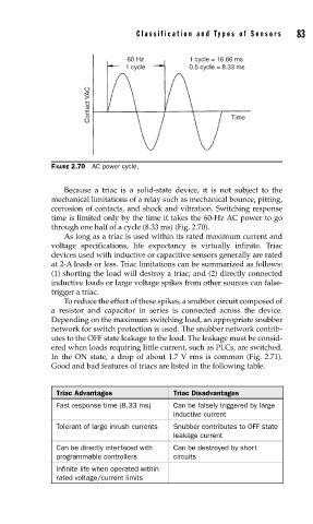
FIGURE 2.70 AC power cycle.
Because a triac is a solid-state device, it is not subject to the
mechanical limitations of a relay such as mechanical bounce, pitting,
corrosion of contacts, and shock and vibration. Switching response
time is limited only by the time it takes the 60-Hz AC power to go
through one half of a cycle (8.33 ms) (Fig. 2.70).
As long as a triac is used within its rated maximum current and
voltage specifications, life expectancy is virtually infinite. Triac
devices used with inductive or capacitive sensors generally are rated
at 2-A loads or less. Triac limitations can be summarized as follows:
(1) shorting the load will destroy a triac; and (2) directly connected
inductive loads or large voltage spikes from other sources can false-
trigger a triac.
To reduce the effect of these spikes, a snubber circuit composed of
a resistor and capacitor in series is connected across the device.
Depending on the maximum switching load, an appropriate snubber
network for switch protection is used. The snubber network contrib-
utes to the OFF state leakage to the load. The leakage must be consid-
ered when loads requiring little current, such as PLCs, are switched.
In the ON state, a drop of about 1.7 V rms is common (Fig. 2.71).
Good and bad features of triacs are listed in the following table.
Triac Advantages Triac Disadvantages
Fast response time (8.33 ms) Can be falsely triggered by large
inductive current
Tolerant of large inrush currents Snubber contributes to OFF state
leakage current
Can be directly interfaced with Can be destroyed by short
programmable controllers circuits
Infinite life when operated within
rated voltage/current limits