Page 125 - Sensors and Control Systems in Manufacturing
P. 125

86
                                    T w o
                           Cha p te r

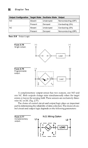
                      Output Configuration Target State Oscillator State Output
                      NO                Absent     Undamped      Nonconducting (OFF)
                                        Present    Damped        Conducting (ON)
                      NC                Absent     Undamped      Conducting (ON)
                                        Present    Damped        Nonconducting (OFF)

                     TABLE 2.8  Output Logic


                          FIGURE 2.75       (+)                           (–)
                          Single output.


                                                                 Load


                          FIGURE 2.76       L1                             L2
                          Programmable
                          output.
                                               1           2
                                                                  Load
                                               3           4


                             A complementary output sensor has two outputs, one NO and
                          one NC. Both outputs change state simultaneously when the target
                          enters or leaves the sensing field. These sensors are exclusively three-
                          wire AC or DC (Fig. 2.77).
                             The choice of control circuit and output logic plays an important
                          part in determining the reliability of data collection. The choice of con-
                          trol circuit and output logic depends on the following parameters:


                          FIGURE 2.77
                          Complementary
                          output.
   120   121   122   123   124   125   126   127   128   129   130