
Page 129 - Sensors and Control Systems in Manufacturing
P. 129
90
Cha p te r
A T w o B C Out
0 0 0 0
0 0 1 1
0 1 0 1
1 0 0 1
TABLE 2.9 Binary Logic Chart–Parallel Connection
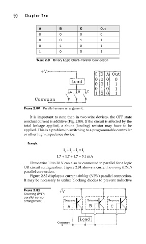
FIGURE 2.80 Parallel sensor arrangement.
It is important to note that, in two-wire devices, the OFF state
residual current is additive (Fig. 2.80). If the circuit is affected by the
total leakage applied, a shunt (loading) resistor may have to be
applied. This is a problem in switching to a programmable controller
or other high-impedance device.
Example.
I + I + I = I
a b c t
1.7 + 1.7 + 1.7 = 5.1 mA
Three-wire 10 to 30 V can also be connected in parallel for a logic
OR circuit configuration. Figure 2.81 shows a current sourcing (PNP)
parallel connection.
Figure 2.82 displays a current sinking (NPN) parallel connection.
It may be necessary to utilize blocking diodes to prevent inductive
FIGURE 2.81
Sourcing (PNP)
parallel sensor
arrangement.