
Page 134 - Sensors and Control Systems in Manufacturing
P. 134
In Classification and Types of Sensors 95
Target
Out
Sensor response Sensor release
time time
On
Sensor
Off
Load response Load release
time time
On
Load
Off
Total response Total release
time time
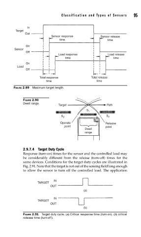
FIGURE 2.89 Maximum target length.
FIGURE 2.90
Dwell range.
Target Path
S 1
S 2 S 2
Operate Release
point point
Dwell
range
2.9.7.4 Target Duty Cycle
Response (turn-on) times for the sensor and the controlled load may
be considerably different from the release (turn-off) times for the
same devices. Conditions for the target duty cycles are illustrated in
Fig. 2.91. Note that the target is not out of the sensing field long enough
to allow the sensor to turn off the controlled load. The application
IN
TARGET
OUT
(a)
IN
TARGET
OUT
(b)
FIGURE 2.91 Target duty cycle. (a) Critical response time (turn-on). (b) critical
release time (turn-off).