
Page 135 - Sensors and Control Systems in Manufacturing
P. 135
96
Cha p te r
T w o
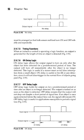
Input signal
Output signal
No delay
FIGURE 2.92 No delay.
must be arranged so that both sensor and load turn ON and OFF reli-
ably and repeatedly.
2.9.7.5 Timing Functions
When an inductive control is operating a logic function, an output is
generated for the length of time an object is detected (Fig. 2.92).
2.9.7.6 ON Delay Logic
ON delay logic allows the output signal to turn on only after the
object has been detected for a predetermined period of time. The
output will turn off immediately after the object is no longer
detected. This logic is useful if a sensor must avoid false interrup-
tion from a small object. ON delay is useful in bin fill or jam detec-
tion, since it will not false-trigger in the normal flow of objects going
past (Fig. 2.93).
2.9.7.7 OFF Delay Logic
OFF delay logic holds the output on for a predetermined period of
time after an object is no longer detected. The output is turned on as
soon as the object is detected. OFF delay ensures that the output will
not drop out despite a short period of signal loss. If an object is once
again detected before the output time out, the signal will remain ON.
OFF delay logic is useful in applications susceptible to periodic signal
loss (Fig. 2.94).
Input signal
Output signal
on delay on delay
FIGURE 2.93 ON delay.